Back
Contact us

7 Best High Pressure Relief Valves for 2026?

Choosing a high pressure relief valve is not just a matter of picking the highest pressure rating. The right model must match the system’s operating pressure, flow requirements, fluid, and connection type. A mismatch can cause nuisance discharge, poor protection, or premature wear. Small details matter.

This guide introduces seven options to consider in 2026, with attention to pressure range, construction materials, adjustment features, and practical installation needs. These factors can help narrow a shortlist, but product specifications should always be checked against the manufacturer’s current documentation. Ratings may differ by model, configuration, and service conditions. A valve described as suitable for one application may not be suitable for another.

Look closely at the pressure setting and rated capacity, not just the product name. Consider whether the valve handles the system’s media and temperature, and whether its inlet and outlet connections fit the installation. The surrounding equipment matters, too. Pipe layout, vibration, and access for inspection can affect real-world performance. Not every valve fits.

The options in this overview are starting points, not a substitute for system-specific engineering review. Where protection depends on precise sizing, consult a qualified professional and follow the applicable manufacturer guidance. Some trade-offs are unavoidable. A compact design may save space but offer fewer adjustment choices. That judgment is not perfect; careful comparison is still worthwhile.
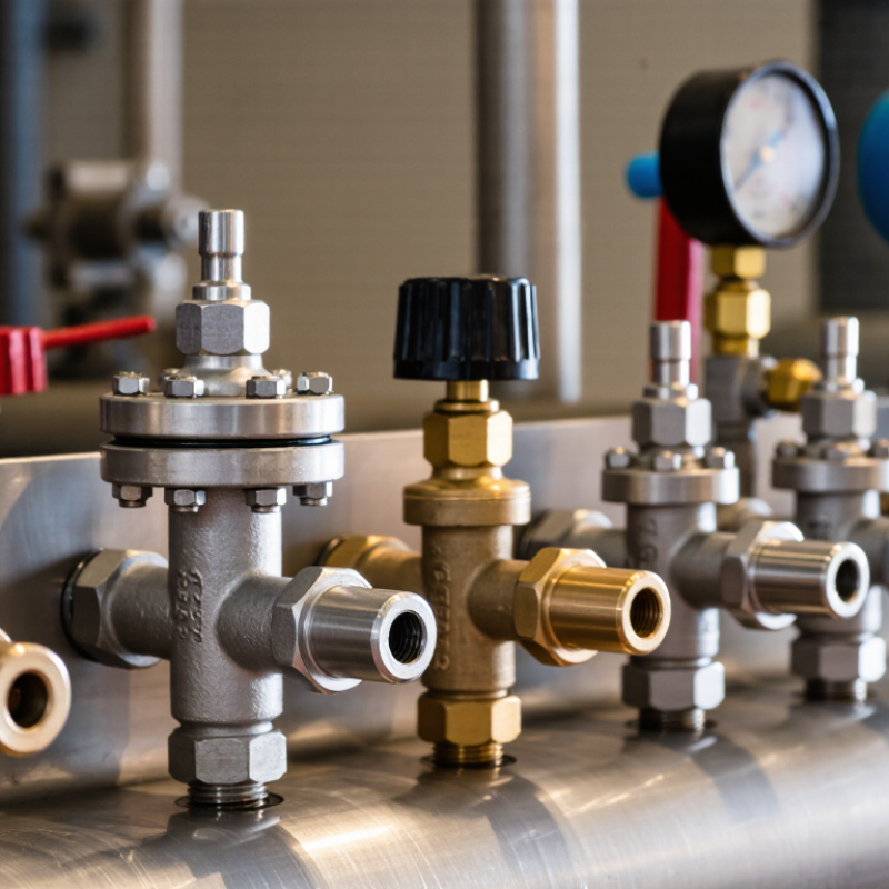
7 Best High Pressure Relief Valves for 2026?

What High-Pressure Relief Valves Do and How They Work

A high-pressure relief valve protects equipment when pressure rises beyond a chosen limit. In a sealed pipe or vessel, excess pressure can strain joints, distort walls, or damage connected instruments. The valve senses upstream pressure and opens when it reaches its set point. Fluid then passes through an outlet, reducing pressure. That is the safeguard.

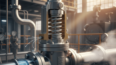
In a spring-loaded design, process pressure pushes against a disc while a spring holds it closed. Once pressure overcomes the spring force, the disc lifts and flow escapes. As pressure falls, the spring helps the valve reseat. Pilot-operated designs use a smaller control valve to manage the main valve, which can suit some high-pressure systems. The details matter. A relief valve is not a pressure regulator; it protects against overpressure rather than continuously controlling normal operating pressure.

Selection depends on more than the set point. Engineers consider flow capacity, fluid properties, operating temperature, backpressure, and the pressure rating of the protected equipment. For example, a valve handling hot, corrosive liquid may need different materials than one used for clean gas. Discharge piping also needs proper sizing and a safe destination. A small installation detail can change performance. Inspection and testing help identify sticking, corrosion, or leakage, though site conditions can make maintenance intervals difficult to judge.
High-Pressure Relief Valves: Pressure and Force

A relief valve opens when system pressure reaches its set point, diverting fluid to help limit pressure. This chart shows the force exerted by different pressures on a 1 cm² area—a useful illustration of why pressure-rated components and correct valve sizing matter.

Illustrative calculations: 1 bar acting on 1 cm² produces 10 N of force. The examples are not valve ratings or recommended set pressures; actual specifications depend on the system and applicable standards.

How to Evaluate High-Pressure Relief Valves in 2026

7 Best High Pressure Relief Valves for 2026?
How to Evaluate High-Pressure Relief Valves in 2026

A relief valve should match the system’s maximum allowable working pressure, fluid, temperature, and required discharge capacity. Start with documented set-pressure and capacity data, then compare them with the equipment’s operating conditions. ASME BPVC Section VIII specifies a set-pressure tolerance of ±3% for many valves set above 70 psi; at 70 psi or below, the tolerance is ±2 psi. Check the applicable code and valve certification before treating those limits as universal.

Capacity is only part of the assessment. API 520 and API 521 provide industry guidance for sizing pressure-relief devices and evaluating installation conditions. Confirm the stated capacity against the required relieving rate, and inspect inlet pressure drop, backpressure, and discharge piping. A crowded pipe run can affect performance. So can a fluid that differs from the one used for published test data.

Review materials, temperature limits, seal compatibility, inspection intervals, and test records. Look for traceable certification and clear maintenance instructions, not just a high-pressure rating on a datasheet. A tidy specification sheet can still leave important questions unanswered. Ask how the valve behaves under the actual service conditions, and have a qualified engineer verify sizing and installation against the applicable edition of the standards.

Seven High-Pressure Relief Valves to Consider in 2026

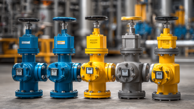
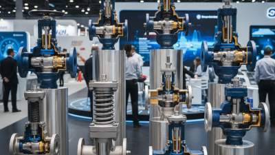
Seven high-pressure relief valve configurations deserve consideration in 2026: conventional spring-loaded, balanced-bellows, pilot-operated, modulating pilot-operated, proportional-lift, thermal-expansion, and rupture-disc/valve combinations. Each fits a different pressure range, fluid, and operating pattern. A conventional spring design is familiar and straightforward to inspect; a balanced bellows can reduce the effect of backpressure. Pilot-operated designs suit some high-pressure applications, but dirty or viscous fluids may complicate reliable operation. Thermal relief protects liquid-filled sections where heat can raise pressure. Small detail, big consequence.

API 520 Part I and II provide recognized guidance for sizing and installation, including discharge piping and backpressure. Treat those calculations as design inputs, not a substitute for checking actual process conditions. The U.S. Chemical Safety Board’s 2007 investigation of the Texas City refinery explosion recorded 15 deaths and 180 injuries; its findings highlighted serious weaknesses in process design and safeguards. The incident was not simply a valve-selection failure, but it shows why relief paths and discharge locations deserve close review. Before choosing, verify set pressure, required capacity, fluid phase, temperature, corrosion risk, and maintenance access. I would not select by pressure rating alone; that shortcut looks tidy, but misses the system. A final check against operating records can expose recurring leaks or pressure spikes that drawings do not show.

7 Best High Pressure Relief Valves for 2026? - Seven High-Pressure Relief Valves to Consider in 2026

Valve Configuration Operating Principle Potential Application Backpressure Consideration Key Selection Checks
Conventional spring-loaded A spring holds the disc against the seat until inlet pressure reaches the set pressure. A straightforward option for systems where discharge conditions and allowable backpressure are well controlled. Superimposed backpressure can affect set pressure; built-up backpressure can affect capacity and operation. Set pressure, relieving capacity, inlet losses, discharge piping, fluid phase, and allowable backpressure.
Balanced-bellows spring-loaded A bellows arrangement reduces the effect of backpressure on the valve’s spring and disc. Systems with variable or higher discharge-header backpressure, when the selected design is compatible with the service. Designed to reduce backpressure effects, but allowable limits still depend on the specific valve and installation. Bellows pressure limits, corrosion compatibility, venting, temperature, and manufacturer-stated capacity corrections.
Balanced-piston spring-loaded A piston-style balancing feature helps limit the influence of backpressure on the moving assembly. Some applications requiring a balanced design where the construction is suitable for the process fluid and operating conditions. Balancing can reduce sensitivity, but does not eliminate the need to verify permitted backpressure. Seal and piston compatibility, leakage tolerance, pressure and temperature limits, and certified capacity data.
Pilot-operated A pilot controls pressure in the main valve chamber; system pressure operates the main valve when relief is required. Potentially suitable for applications needing tight operating margins or high capacity in a compact nominal size, subject to design limits. Some designs tolerate substantial backpressure; performance depends on pilot arrangement and the specific product design. Pilot type, sensing line arrangement, contamination or freezing risk, minimum operating pressure, and fail-safe behavior.
Thermal expansion relief A small relief valve opens to protect liquid trapped in a blocked-in section as temperature-driven expansion raises pressure. Blocked-in liquid piping, equipment, or other enclosed liquid volumes where thermal expansion is a credible overpressure cause. Discharge routing matters; backpressure and outlet conditions must remain within the valve’s specified limits. Thermal expansion scenario, set pressure, small required relief rate, fluid compatibility, and safe discharge destination.
Spring-loaded valve for gas or vapor service A spring-loaded mechanism relieves compressible fluid; sizing accounts for gas or vapor properties and certified flow performance. Gas and vapor systems when the selected valve is rated and sized for the fluid, relieving conditions, and required capacity. Discharge backpressure can influence operation and capacity; assess the complete outlet system. Molecular weight, compressibility, temperature, relieving pressure, required capacity, and applicable capacity corrections.
Pilot-operated valve for liquid service A pilot initiates opening of the main valve; liquid-service behavior and capacity depend on the selected design. Liquid systems where a pilot-operated design is specifically approved for the fluid and operating conditions. Verify allowable backpressure and discharge arrangements; liquid flow can create significant outlet forces and pressure losses. Liquid properties, required capacity, cavitation or flashing risk, pilot compatibility, and relief destination.

Selection note: These are generic valve configurations, not a ranked list of specific products. No single pressure range applies to every design. Confirm set pressure, certified relieving capacity, materials, temperature limits, backpressure, installation details, and applicable codes with the equipment documentation and a qualified pressure-relief specialist. ASME Section VIII and API 520/521 may be relevant depending on the equipment, jurisdiction, and application.

Comparing Valve Types, Pressure Ratings, and Applications

High-pressure relief valves differ in response, reseating, and sensitivity to outlet pressure. Spring-loaded designs are mechanically simple and suit many gas or liquid systems. Pilot-operated valves can handle higher inlet pressures and maintain tight shutoff near set pressure, but their pilot passages need clean fluids. Balanced-bellows designs help where backpressure varies. Rupture disks open quickly and do not reseat. That matters. A discharge may continue until the system is isolated.

Pressure ratings need careful reading. ASME pressure class is not the valve’s set pressure; allowable pressure also changes with material and temperature. API 520 Part I provides sizing guidance, while ASME BPVC Section VIII sets pressure-relief requirements. For common non-fire cases, Section VIII generally permits 10% accumulation with one relief device; fire exposure can allow 21%. These figures are not universal operating targets. Match set pressure to the protected equipment, then check capacity, inlet losses, backpressure, and fluid phase. On a hot compressor line, for example, a valve sized only from normal flow may fail to protect during a blocked discharge. I would still verify the actual service data: that step is easy to rush, and it can change the selection.

Installation, Testing, and Maintenance for Safe Operation

A high-pressure relief valve protects equipment only when it is correctly selected, installed, and maintained. Confirm that its pressure rating and capacity suit the system’s operating conditions. Before installation, isolate the equipment and verify that pressure has been safely released. Small details matter. Keep the inlet and discharge paths unobstructed, and support connected piping so its weight does not strain the valve.

Testing should follow the valve maker’s instructions and the site’s approved procedures. Have qualified personnel use calibrated equipment and suitable protective measures. Check that the valve opens and reseats as specified, without forcing parts or changing settings casually. Record the test date, measured results, and any adjustments. A clean-looking valve is not proof that it will perform under pressure.

Build maintenance around operating conditions, service history, and inspection findings. Look for corrosion, leakage, damaged seals, loose connections, and signs of vibration. Check discharge piping for blockages or deposits, especially after process changes. Replace or repair components only with compatible parts, then document the work and retest as required. Even a careful checklist can miss a hidden problem; reviewing recurring failures and questioning old assumptions helps keep the inspection plan useful.