Back
Contact us

7 Tips for Choosing the Right Hydraulic Actuator

Choosing the right hydraulic actuator is not a catalog exercise. It is a decision about load, motion, pressure, duty cycle, and the environment around the machine. A cylinder that looks adequate on paper may stall under side loading, run too slowly, or wear early when contamination enters the system. Small details matter. A wet washdown area, a long stroke, or frequent starts can change the specification.

Industry context helps, but it cannot replace application data. The National Fluid Power Association’s industry shipment and order reports track activity across the fluid-power sector; they do not identify the best actuator for a particular machine. The U.S. Department of Energy’s Improving Pumping System Performance sourcebook also explains why system-level efficiency matters. In practical terms, pressure losses, flow demand, and control choices affect performance beyond the actuator itself. Herbert E. Merritt, author of Hydraulic Control Systems, offers a useful engineering lens: assess the actuator as part of the complete hydraulic system, rather than as an isolated component. That is a paraphrase, not a direct quotation.

This guide presents seven tips for comparing actuator types, calculating force and stroke, checking mounting and alignment, and reviewing fluid, seals, and maintenance access. Start with the load. Then verify operating pressure, required speed, and cycle frequency against the machine’s real conditions. A poor fit costs. Yet no checklist can replace measured data or a qualified engineering review, and that limitation deserves attention. Use the tips to ask better questions before specifying or purchasing a hydraulic actuator.

7 Tips for Choosing the Right Hydraulic Actuator

Identify the Load, Motion, and Operating Requirements

7 Tips for Choosing the Right Hydraulic Actuator

Identify the Load, Motion, and Operating Requirements

Tip 1: Define the real load.

Record the weight, direction, and whether the actuator must push, pull, lift, or hold. Include friction and any side loads; a load that moves smoothly by hand may resist under production conditions. It is tempting to size from weight alone. That shortcut can be misleading. Measure it twice.

Tip 2: Match the motion.

Note the required stroke, speed, and cycle frequency. For example, a press may need steady force near the end of its travel, while a gate may need controlled movement throughout. Check available space and mounting points, too. A long stroke in a tight frame can create alignment problems. Small details matter.

Tip 3: Describe the operating conditions.

Identify fluid type, pressure range, temperature, contamination, and expected duty cycle. A unit used outdoors may face moisture and temperature swings; a continuously cycling machine may need different heat management. Specify how the actuator should behave if power or pressure is lost. These requirements are sometimes overlooked, and that is worth reviewing before selection. Confirm force and mounting calculations with qualified engineering support, especially when people or equipment could be exposed to a moving load.
Compare Hydraulic Actuator Types and Their Functions

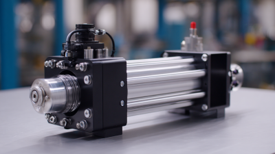
Hydraulic actuators convert pressurized fluid into controlled motion, but each type serves a different task. Single-acting cylinders move under pressure in one direction and return by spring or load. Double-acting cylinders use pressure on both sides for controlled extension and retraction. Telescopic cylinders provide long travel from a compact retracted length, often useful on lifting platforms. Hydraulic motors and rotary actuators produce turning motion rather than a straight stroke.

Tip: Choose the motion first. A 500-millimeter stroke may suit a telescopic cylinder, while a rotary actuator may better fit a valve shaft. Then check force, operating pressure, duty cycle, mounting, and side loading. A mismatch can cause rod wear or uneven seals. Details matter.

The U.S. Department of Energy’s 2006 Improving Pumping System Performance sourcebook reports that pumping systems use nearly 20% of global electricity demand. That figure is not specific to actuators, but it highlights why system efficiency deserves attention. A small cylinder leak or oversized actuator can waste energy over repeated cycles.

Tip: Compare the full duty cycle, not just peak force. Record load, stroke speed, cycle frequency, and fluid conditions; real installations rarely behave exactly like a clean calculation.

Calculate the Required Force, Speed, and Stroke

Tip 1: Calculate force from pressure and piston area: F = P × A. Use the pressure available at the actuator, not just the pump’s rated pressure. Allow for friction, pressure losses, and changing loads. On a retracting stroke, calculate with the smaller annular area around the rod. A 50 mm bore at 160 bar produces about 31 kN theoretically, before losses. That number is a starting point, not a guaranteed working force.

Tip 2: Set speed from required flow and effective area: v = Q ÷ A. A larger piston moves more slowly at the same flow. Check that the pump, valves, and hoses can supply the needed flow without excessive pressure drop. Account for both extension and retraction speeds; the rod-side area makes them different. Real loads also vary. A clean calculation may miss a sticky linkage or a sudden load change.

Tip 3: Measure the actual stroke between working positions, then check mounting geometry across the full movement. Include clearance for pins, brackets, and any end cushioning. Don’t choose stroke from the drawing alone; pivoting parts can change the required travel. A few millimeters matter. Recheck the dimensions on the machine, especially if wear or misalignment is present.

Check Pressure, Fluid Compatibility, and Environmental Conditions

Choosing a hydraulic actuator starts with the pressure it will actually face. Check normal operating pressure, startup spikes, and relief-valve settings; a pump’s nominal rating alone can hide brief overloads. ISO 4413:2010 sets safety requirements for hydraulic systems, including pressure-related design considerations. Match the actuator’s rated pressure to the system, then leave a practical margin. Small pressure peaks matter.

Fluid compatibility is just as important. Confirm that the fluid suits the actuator’s seals and materials, especially when changing from mineral oil to a water-glycol or biodegradable fluid. ISO 4406:2021 classifies hydraulic-fluid cleanliness by particle counts at 4, 6, and 14 μm(c). Use the equipment maker’s cleanliness target, and check filtration rather than assuming new fluid is clean.

Finally, look at the real environment: cold starts, hot enclosures, washdown, dust, and corrosive spray can all affect seals and service life. Record temperature extremes and inspect the installation for moisture or grit. I would recheck fluid and seal compatibility after any process change; it is easy to overlook. A pressure gauge reading during steady operation will not reveal every transient, so test under realistic load conditions where possible.

Hydraulic Actuator Selection: Hydraulic Oil Viscosity Grades

ISO VG numbers indicate the nominal kinematic viscosity of industrial lubricants at 40°C, in mm²/s (cSt). Choose fluid that meets the actuator and pump specifications, and verify seal compatibility, operating temperature, pressure rating, and environmental exposure. The viscosity grade alone does not confirm fluid compatibility.

Evaluate Mounting, Controls, Safety, and Maintenance Needs

A hydraulic actuator may have enough force on paper, yet still perform poorly if its mounting does not match the machine. Check pin diameter, stroke, and available clearance against the actual installation, not just the drawing. Clevis mounts allow pivoting movement, while rigid mounts need careful alignment. A small angle error can create side load, uneven seal wear, and early leakage. That matters.

Controls shape how the actuator behaves during real work. Confirm the system’s pressure and flow range, then consider how speed will be adjusted. A directional valve may be sufficient for simple movement, but applications needing precise positioning may require feedback sensors. Think about what happens when power is lost, too. The right control setup depends on the load and duty cycle; there is no universal answer.

Safety and maintenance deserve the same attention as force and stroke. Check the actuator’s pressure rating and how the load is held when the system stops. Guards, hose routing, and accessible isolation points can reduce risks during operation and service. Plan room to inspect seals, fittings, and mounting pins without dismantling nearby equipment. Clean hydraulic fluid is essential, so include filtration and contamination checks in the maintenance plan. Small details count. I have seen selection plans look complete until someone tries to reach a fitting with a wrench. A quick service-access review can catch that before installation.

7 Tips for Choosing the Right Hydraulic Actuator - Evaluate Mounting, Controls, Safety, and Maintenance Needs
No. Selection Tip What to Evaluate Practical Check
1 Define the required force and motion Determine the load, direction of force, stroke length, movement speed, and duty cycle. Account for friction, acceleration, and any changing loads. Compare the calculated operating requirements with the actuator’s rated pressure, force, stroke, and speed. Include an appropriate engineering margin rather than sizing from the load alone.
2 Check the mounting arrangement Review available space, pivot points, alignment, pin or flange connections, and how the actuator will be supported throughout its stroke. Confirm that the mounting can withstand the expected forces and that the actuator will not be subjected to unintended side loads. Use suitable articulation where the motion requires it.
3 Match the hydraulic supply Check system pressure, available flow, fluid type, operating temperature, and port and hose connections. Verify that the power unit and control valves can provide the required pressure and flow. Confirm fluid compatibility and follow the actuator and system manufacturers’ specifications.
4 Choose suitable controls Decide whether motion needs to be manually operated, electrically controlled, proportional, or integrated with an automated system. Identify the required direction, speed adjustment, end-of-travel behavior, and feedback. Select valves and sensors that are compatible with the hydraulic circuit and control system.
5 Plan for safe operation Consider load holding, unexpected movement, pressure spikes, hose failure, emergency stopping, and access to pinch or crush points. Assess whether the application needs load-holding valves, pressure relief, guarding, or other protective measures. Have the complete machine risk assessment reviewed by a qualified person.
6 Account for the operating environment Evaluate dust, moisture, corrosive substances, temperature extremes, vibration, and exposure to impact or contamination. Check that materials, seals, coatings, and protection features suit the environment. Protect hydraulic connections and keep the system fluid clean to reduce wear and seal damage.
7 Review maintenance and service access Consider inspection intervals, seal and fluid servicing, spare-part availability, and the space needed to remove or repair the actuator. Plan safe isolation and pressure release before service. Confirm that inspection points and connections are accessible, and follow the equipment documentation for maintenance requirements.