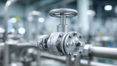
Selecting the right wafer valve can determine whether a piping system runs smoothly or develops costly problems. The choice affects flow control, sealing performance, maintenance time, and equipment life. A valve may look suitable on a drawing, yet fail when exposed to abrasive media, repeated cycling, or sudden temperature changes.
Experienced engineers usually begin with the process, not the product catalog. They check fluid type, pressure, temperature, pipe size, flow direction, and installation space. For example, a compact wafer valve may fit neatly between two flanges in a crowded pump room. However, its seat material must also resist the actual chemical or slurry passing through the line. Small details matter. A mismatched elastomer can swell, crack, or leak within months.
Reliable selection also requires verified technical information. Review pressure ratings, face-to-face dimensions, actuator compatibility, body materials, and applicable industry standards. Manufacturer test records and clear installation instructions add practical confidence. Still, no datasheet replaces field judgment. Site conditions are often less tidy than expected, and previous assumptions may be wrong. That deserves attention.
This guide explains how to compare wafer valve designs for different systems. It considers media compatibility, operating conditions, control requirements, maintenance access, and total ownership cost. The goal is not to recommend the most expensive valve. It is to identify the safest, most dependable option for the real application, including the details that are easy to overlook.
How to Choose the Right Wafer Valve for Your System?
Before selecting a wafer valve, define the system’s actual flow, pressure, and temperature requirements. Do not rely only on the pipe diameter. A 100-millimeter line may carry clean water, abrasive slurry, or compressed gas. Each service demands a different valve design.
Record the normal, minimum, and maximum flow rates. Then check the required pressure drop across the valve. Excessive restriction can reduce pump efficiency and create unwanted noise. Measure both working pressure and possible pressure surges. A line operating at 6 bar may experience a much higher transient load during rapid closure. Temperature also matters. Consider startup conditions, cleaning cycles, and unexpected heat exposure. Valve materials and seals must remain stable across the full temperature range.
Tips: Build a simple service table before requesting technical data. Include medium, flow rate, pressure, temperature, pipe size, and operating frequency. Note whether the medium contains solids. Small particles can change sealing performance over time. Check compatibility carefully. A familiar material is not always suitable.
I have seen projects fail because engineers used normal operating values only. That approach is understandable, but incomplete. Review the worst credible conditions and the required shutoff class. Confirm face-to-face dimensions, flange compatibility, actuator torque, and installation space. Ask for certified pressure and temperature ratings. If the data is uncertain, mark it as uncertain rather than guessing. That small note can prevent a costly replacement.
Choosing a wafer valve starts with its operating principle, not its compact appearance. A butterfly valve rotates a disc around a central stem. It opens quickly, needs little space, and controls flow reasonably well. Soft seats suit clean water and compatible fluids. Metal seats handle higher temperatures, but sealing can be less forgiving. Double-offset designs reduce seat contact during rotation, which may improve service life.
A wafer check valve works without an actuator. Flow pressure lifts or swings the closing element, while reverse flow returns it to the seat. Dual-plate versions are short and lightweight. They can reduce water hammer when correctly sized. A wafer gate valve moves a plate linearly across the passage. It provides strong isolation, not precise throttling. Sediment can obstruct its seating area. That detail is easy to miss.
In practice, compare pressure class, temperature, media cleanliness, cycling frequency, and installation space. Check disc, seat, and body materials against corrosion data, not assumptions. Abrasive particles can quickly damage a poorly selected seat. Pulsating flow may make a check valve chatter if closing force is insufficient. Verify face-to-face dimensions and downstream clearances before ordering. Field inspections often reveal misalignment or unsupported piping. These defects can distort the valve and create leaks. I would still recheck every selection against actual operating records, because catalog conditions rarely match every startup and shutdown.
Comparison of common wafer valve types by representative maximum pressure rating
A rotating disc controls flow with a quarter-turn motion. It is compact, lightweight, and commonly used for isolation and moderate throttling in water, HVAC, and process systems.
Spring-loaded discs or plates open in the forward-flow direction and close automatically when flow reverses. It prevents backflow without external actuation.
A sliding gate moves vertically through the media to provide on/off isolation. It is suited to slurries, powders, and fluids containing suspended solids, but is generally not intended for precise throttling.
The chart shows representative maximum nominal pressure ratings commonly available in wafer-style designs: PN10 = 10 bar, PN16 = 16 bar, PN25 = 25 bar, and PN40 = 40 bar. Actual ratings depend on valve construction, materials, temperature, standards, and service conditions.
Material selection should begin with the fluid, not the valve size. Check pH, chlorides, solids, temperature, pressure, and cleaning chemicals. A stainless-steel body is not automatically safer. Chloride-rich water can still cause pitting, especially at higher temperatures. For abrasive slurries, inspect the disc edge and seat for erosion resistance. Seat materials also matter. PTFE handles many chemicals, while elastomers may perform better under repeated cycling. Always confirm compatibility using tested chemical-resistance data, not a general material chart.
Corrosion deserves serious attention. The NACE IMPACT study estimated global corrosion costs at US$2.5 trillion annually, equal to about 3.4% of global GDP. Material mistakes are expensive. In water systems, the U.S. EPA’s 2023 7th Drinking Water Infrastructure Needs Survey projected US$625 billion in needs through 2040. That scale makes durability a design issue, not a purchasing detail. Specify wetted materials separately from the body, including the stem, disc, seat, and liner. Ask for temperature limits, pressure ratings, test records, and chemical exposure history. In field reviews, engineers sometimes over-select exotic alloys without checking gasket compatibility. That choice can add cost without improving service life. Reconsider it. A practical selection records the actual fluid concentration, operating cycle, and upset conditions before approval.
How to Choose the Right Wafer Valve for Your System?
Evaluate Valve Size, Actuation, Installation, and Maintenance Needs
A wafer valve should match the system’s real flow conditions, not only the pipe diameter. A slightly oversized valve may control poorly and create unstable flow. An undersized valve can cause excessive pressure loss. Check the medium, temperature, pressure, flow rate, and required shutoff performance. One practical lesson from maintenance reviews is simple: nominal size rarely tells the whole story. It is only the starting point.
Actuation also deserves careful attention. Manual handles suit small valves and occasional operation. Pneumatic actuators work well for frequent cycling and rapid response. Electric actuators may support remote control, but they need suitable power and environmental protection. Confirm the required torque under the worst operating conditions. Do not rely on catalog figures alone. A safety margin is necessary, but excessive sizing can increase cost and wear.
Installation details often decide long-term reliability. Inspect flange faces, align the pipe carefully, and tighten bolts evenly. Never force a valve into a distorted pipeline. Leave enough clearance for the actuator, handle, and future service work. During maintenance, examine the stem, seat, body, and fasteners for wear or corrosion. Cycle the valve periodically when the process allows it. Records should include operating problems, replacement parts, and inspection dates. Teams sometimes overlook access space, then discover that a simple seat inspection requires partial disassembly. That mistake is avoidable, but not always avoided.
How to Choose the Right Wafer Valve for Your System?
Choosing a wafer valve starts with verified standards, not a catalog photograph. Confirm the required pressure class, flange dimensions, testing methods, and material traceability. Standards such as ISO, EN, or ASME may apply, depending on the installation and market. Request inspection records and pressure-test certificates. Small documentation gaps can become expensive compliance problems.
Compatibility requires more than matching pipe size. Check the fluid, temperature range, pressure, flow direction, and corrosion risks. A valve handling clean water may fail quickly in abrasive slurry. For vacuum service, seat design and leakage performance need special attention. Consider actuator torque, available space, and emergency access around the line. Measure twice.
Reliability depends on cycling, maintenance, and manufacturing control. Ask how the valve was tested, how many operating cycles it supports, and whether replacement parts remain available. Total cost of ownership includes installation, actuation energy, inspections, spare parts, downtime, and disposal. A cheaper valve can demand frequent shutdowns. That calculation is often missed. Engineers should also review real operating data after installation, because assumptions about temperature or cycling may prove wrong. No selection method is perfect; honest records and periodic review usually prevent a small mismatch from becoming a major failure.
| Decision Dimension | What to Verify | Relevant Standard or Reference | Suitable Selection Guidance | Risk if Incorrect |
|---|---|---|---|---|
| Valve Function | Confirm whether the valve is required for isolation, throttling, non-return protection, or emergency shutoff. | Project specifications; process-control philosophy; applicable piping code. | Use a resilient- or metal-seated butterfly valve for compact isolation; use a control-rated design only when the manufacturer provides suitable flow-control data. | Premature seat damage, unstable flow control, excessive pressure loss, or inability to achieve tight shutoff. |
| Applicable Standards | Check design, face-to-face, pressure-testing, marking, and conformity requirements. | API 609 or EN 593 for butterfly valves; MSS SP-67 for butterfly valves; API 598 or ISO 5208 for pressure testing; ISO 5211 for actuator mounting. | Select valves with documented compliance to the standards required by the project, jurisdiction, and end user. | Rejected equipment, failed inspection, unclear performance limits, or non-compliance with contractual requirements. |
| Pressure Rating | Compare maximum allowable working pressure with operating, design, surge, and test pressures at the actual temperature. | ASME B16.5 or ASME B16.47 flange ratings; EN 1092-1 flange ratings; valve-specific pressure-temperature chart. | Never select from nominal pressure alone. Confirm the complete pressure-temperature rating for the body, seat, disc, shaft, and liner. | Leakage, deformation, pressure-boundary failure, or reduced service life. |
| Flange and Dimensional Compatibility | Verify nominal size, flange type, pressure class, bolt pattern, inside diameter, face-to-face length, and available installation space. | ASME B16.5; ASME B16.47; EN 1092-1; EN 558 for face-to-face dimensions; ISO 5752 where specified. | Confirm that the disc can rotate freely without contacting the pipe bore, flange, liner, or downstream equipment. | Installation failure, damaged sealing surfaces, restricted flow, or disc interference. |
| Process Fluid Compatibility | Evaluate chemical concentration, pH, solids content, abrasiveness, viscosity, toxicity, and cleanliness requirements. | Material compatibility data; NACE MR0175/ISO 15156 when applicable to sour service; project chemical-resistance requirements. | Match body, disc, shaft, seat, liner, and elastomers to the fluid. Do not assess compatibility from body material alone. | Corrosion, swelling, embrittlement, erosion, contamination, or loss of sealing capability. |
| Temperature Range | Confirm minimum and maximum process, ambient, start-up, shutdown, and cleaning temperatures. | Manufacturer pressure-temperature data; ASTM material specifications; applicable cryogenic or high-temperature project requirements. | Use elastomers and liners only within their documented continuous and intermittent temperature limits. Consider thermal cycling separately. | Seat hardening, softening, cracking, leakage, or actuator torque changes. |
| Tight-Shutoff Requirement | Define allowable leakage, pressure direction, bidirectional or unidirectional service, and isolation time. | ISO 5208; API 598; MSS SP-61 where applicable; project leakage class requirements. | Choose a seat design and test pressure that meet the specified leakage class at the actual operating conditions. | Unsafe isolation, product loss, cross-contamination, or inability to perform maintenance safely. |
| Flow and Pressure Loss | Review flow rate, velocity, pressure drop, cavitation risk, noise, and operating position. | Manufacturer Cv or Kv data; IEC 60534-2-1 for control-valve flow calculations where applicable. | Size the valve using verified flow coefficients and avoid prolonged operation near positions where flow instability or high velocity may occur. | Higher pumping energy, vibration, noise, cavitation, and accelerated seat or disc wear. |
| Actuation and Torque | Calculate breakaway, running, seating, unseating, emergency, and maximum shaft torque, including safety margin. | ISO 5211 for actuator interface; actuator and valve torque documentation; applicable functional-safety specification. | Select manual, pneumatic, electric, or hydraulic actuation based on cycle frequency, fail position, available utilities, and required response time. | Failure to open or close, actuator overload, slow emergency response, or unplanned downtime. |
| Reliability and Cycle Life | Assess operating cycles, duty frequency, vibration, thermal cycling, corrosion exposure, and maintenance history. | Documented endurance-test results; ISO 15848 for fugitive-emission performance where specified; site reliability requirements. | Request cycle-life data under conditions that represent the actual pressure, temperature, fluid, and actuation profile. | Frequent seal replacement, unplanned outages, increased maintenance labor, and safety exposure. |
| Fire-Safe or Emissions Requirements | Determine whether the service involves flammable fluids, toxic emissions, or regulated leakage limits. | API 607 or ISO 10497 for fire testing where applicable; ISO 15848 for fugitive emissions where specified. | Require valid test evidence for the complete valve configuration, including packing, seat, shaft, and actuator arrangement. | Fire escalation, hazardous exposure, environmental non-compliance, or failed regulatory inspection. |
| Maintenance and Spare Parts | Check seat replacement method, shaft and bearing accessibility, spare-part availability, tooling, and technician requirements. | Maintenance manual; equipment-maintenance strategy; site spare-parts policy. | Prefer standardized components, replaceable soft parts where suitable, clear instructions, and documented torque settings. | Longer maintenance windows, higher inventory costs, incorrect reassembly, or extended downtime. |
| Total Cost of Ownership | Compare purchase price, installation, actuation, energy loss, inspections, spare parts, maintenance labor, downtime, and disposal. | Lifecycle-cost model; internal maintenance and energy rates; reliability and downtime data. | Use: TCO = purchase + installation + energy + maintenance + spares + downtime + disposal. Evaluate the expected service period, not only the initial price. | Low initial cost but higher operating expense, frequent replacement, and greater production losses. |
| Documentation and Traceability | Request datasheets, drawings, material certificates, pressure-test records, calibration certificates, and inspection documentation. | EN 10204 for material certificates where required; project quality plan; inspection and test plan. | Ensure the documents identify the exact valve size, rating, materials, serial number, test standard, and test results. | Difficult audits, uncertain material provenance, installation delays, or inability to prove compliance. |