
Back
Contact us

How to Choose a Heatsink Thermal Pad in 2026?

Choosing a Heatsink Thermal Pad in 2026 is not simply a matter of selecting the highest conductivity rating. The correct pad must match the gap, surface texture, pressure, and heat load of the assembly. A 12 W/m·K pad can perform poorly if it is too thick or compressed unevenly. Small details matter.

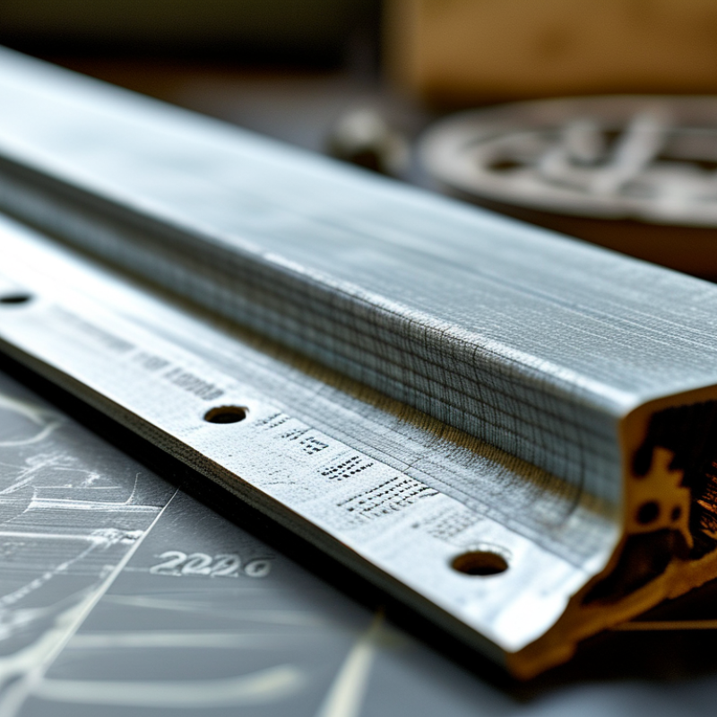
In practical repairs, uneven contact often appears as a bright imprint on one side of the pad. That mark can reveal mounting pressure problems before a temperature test confirms them. Measure the real gap with a feeler gauge or modeling clay, then compare it with the manufacturer’s recommended compression range. Check thermal conductivity, dielectric strength, hardness, thickness tolerance, and operating temperature. A reliable datasheet matters more than a dramatic product claim.

Material choice also depends on the component. Memory modules, power stages, LEDs, and processors may require different softness and insulation behavior. Silicone-based pads are common, but they are not automatically ideal for every enclosure. Some materials creep after repeated heating cycles. Others tear during installation. This is where product testing becomes valuable. Record idle and load temperatures, ambient conditions, fan speed, and mounting torque. Results should be repeatable.

No selection guide can remove every uncertainty. Real surfaces are rarely perfectly flat. Thermal sensors can also mislead. Still, careful measurement and controlled testing create a defensible decision. This guide examines the selection process, common mistakes, installation methods, and performance checks needed for dependable thermal management in 2026.
How to Choose a Heatsink Thermal Pad in 2026?

Define Thermal Pad Materials, Grades, and Heat Transfer Properties

Choosing a Thermal Pad in 2026: Materials, Grades, and Heat Transfer Properties

Choosing a thermal pad starts with the gap, not the product label. Measure the real distance between the heatsink and component with a caliper. Silicone-based pads are flexible, electrically insulating, and suitable for uneven surfaces. Non-silicone pads can suit sensitive assemblies, but their compression and aging behavior may differ. Phase-change materials soften with heat and fill microscopic air gaps. They need controlled assembly.

Grade is more than thermal conductivity. Check conductivity in W/m·K, hardness, thickness tolerance, compression range, dielectric strength, and temperature limits. A soft pad conforms well, yet excessive compression may damage a small component or create uneven pressure. A harder grade transfers heat consistently, but it can leave air pockets on a warped surface. Thermal resistance matters more than a headline number. Estimate it with R = thickness ÷ conductivity ÷ contact area. Interface resistance still affects performance.

During fitting, inspect both surfaces for dust, burrs, and protective film. Use the specified thickness, because stacking pads often traps air. After assembly, check contact marks and monitor temperature under a repeatable load. I would not trust one laboratory value alone. Results can differ with pressure, temperature, and test method. That uncertainty deserves attention. A practical choice balances material stability, electrical safety, gap control, and measured thermal performance.

Measure the Gap and Match the Pad Thickness Correctly

How to Choose a Heatsink Thermal Pad in 2026?

Measure the gap before choosing a thermal pad. Do not estimate it by sight. A small error can create poor contact or excessive pressure on the circuit board. Use a digital caliper to measure the distance between the component surface and the heatsink base. Check several points around the component. Gaps can vary because boards and heatsinks are rarely perfectly flat.

Record the smallest and largest measurements. Then compare them with the pad’s recommended compression range. For example, a 1.5-millimeter gap may require a 2-millimeter pad if the material compresses safely. Follow the technical data, not guesswork.

A pad that is too thin may leave an air pocket. Air is a weak heat conductor. A pad that is too thick may bend the board or reduce heatsink contact.

Clean both surfaces with a suitable lint-free wipe. Remove dust, protective films, and old residue. Place the pad without stretching it. I once trusted one measurement and ignored a corner gap. The installation worked, but heat transfer was uneven. That mistake changed my process. Now I measure corners, inspect compression marks, and recheck mounting pressure. Check the pad after installation. A slight, even imprint usually indicates contact. It is not perfect evidence, but it is useful evidence. Temperature testing under a stable load can confirm the result. Allow the system to reach a steady temperature before judging performance.

Choose the Right Thermal Conductivity for Your Device

How to Choose a Heatsink Thermal Pad in 2026?

Thermal conductivity is the starting point, not the final answer. A pad rated at 12 W/m·K can outperform a 20 W/m·K pad if it fills the gap better. The contact surfaces matter. The U.S. Department of Energy’s 2024 data-center assessment reports that cooling may consume 7% to 30% of facility electricity. Poor heat transfer increases that burden. For a compact processor, begin with the device’s heat output, measured gap, and allowable junction temperature. Then select a pad with suitable conductivity, thickness, and compression.

Do not chase the largest conductivity number. Higher-performance pads may be stiffer, harder to install, or less reliable across uneven surfaces. Measure the gap after assembly if possible. A 1 mm pad squeezed into a 0.5 mm space can create excess mechanical stress. The JEDEC JESD51 thermal-testing standards also emphasize controlled interfaces and repeatable measurement conditions. That matters because advertised conductivity is usually measured under laboratory conditions, not inside a vibrating enclosure.

I prefer testing two thicknesses with thermal sensors near the heat source. Small temperature differences can reveal pressure problems. Electrical isolation must be verified when the pad touches exposed contacts. The International Energy Agency’s Electricity 2024 analysis projects data-center electricity demand could exceed 1,000 TWh by 2026, making efficient thermal design increasingly important. Still, the “best” pad is not always the most conductive. That assumption deserves another review.

How to Choose a Heatsink Thermal Pad in 2026?

Choose the right thermal conductivity for your device and thermal load.

The values show typical thermal-conductivity targets for common device categories. Low-power electronics generally work with 1–3 W/m·K pads, while high-power processors and power modules may require 6–12 W/m·K materials. Thermal conductivity is only one factor: pad thickness, contact pressure, surface flatness, compressibility, and total thermal resistance also affect cooling performance.

Check Compression, Surface Fit, and Long-Term Stability

How to Choose a Heatsink Thermal Pad in 2026?

Thermal conductivity gets attention, but compression often decides whether a pad works. Choose a pad that reaches its specified thickness under the assembly’s real clamp load. ASTM D5470 testing treats pressure, thickness, and contact resistance as linked variables. A 2024 industry review of thermal-management materials reported typical gap-filler conductivity between about 1 and 15 W/m·K. Those numbers are useful. However, they are not interchangeable. A soft 3 W/m·K pad may outperform a rigid 10 W/m·K pad when the surface gap is uneven.

Check the mating surfaces under a light. Deep machining marks can trap air beside the pad. Measure the gap at several points, not only at the center. The pad should compress enough to fill valleys, but it must not buckle around screws or corners. In practical assembly tests, uneven clamping can create visible squeeze-out on one side. I have seen this overlooked during prototype reviews.

Long-term stability needs equal attention. Review compression-set data, oil migration, and thermal-cycle results. IEC 60068-2-14 is commonly used for temperature cycling, while qualification plans often examine 500 or 1,000 cycles. After repeated heating, a pad may harden, shrink, or pump away from the hottest area. Check contact again. A small edge gap can become a serious thermal path. One imperfect step remains common: testing only a new pad at room temperature. Include aged samples, real clamp pressure, and the actual surface finish.

Compare Installation Needs, Safety, Cost, and 2026 Product Standards

Choosing a heatsink thermal pad in 2026 requires more than selecting the highest conductivity number. Measure the gap between the component and heatsink first. A pad that is too thin may leave air pockets. A pad that is too thick can create excessive pressure. I still find this easy to misjudge.

During installation, clean both surfaces with suitable isopropyl alcohol and let them dry completely. Remove protective films carefully. Do not stretch, fold, or repeatedly reposition the pad. Check the required compression range in the technical datasheet. Uneven pressure can leave one corner cooler and another dangerously warm. Small details matter.

Safety should guide the material choice. Confirm electrical insulation, operating temperature, flame rating, and compatibility with nearby plastics. For 2026 purchases, request current compliance documents, batch traceability, and test conditions. Check applicable regional requirements, including restricted-substance and chemical reporting rules. A conductivity value without test thickness is weak evidence. Cost also includes cutting waste, labor, replacement parts, and failed thermal testing. The cheapest sheet may become expensive after rework. In practice, a moderately conductive pad with stable compression often performs better than a premium-looking specification. I once underestimated surface roughness; the result was acceptable, but not repeatable. That was a useful warning.